


ISSN: 0973-7510
E-ISSN: 2581-690X
Contaminants in air and water contribute largely to the occurrence of a number of diseases and health problems. TiO2 has been used as a photo-catalyst in various fields such as water purification, air-filters, disinfection and sterilization. The present study is focused on the synthesis of TiO2 and TiO2 doped nanofibers to achieve highly efficient air filters and to obtain increased surface area to volume ratio and optimize concentration of the Ag and Zn in the main matrix of TiO2 to get the better inhibition of both bacterial and fungal species. The synthesized nanofibers were further characterized by employing the standard techniques such as FTIR, SEM and X-RD for Chemical, Morphological and for Structural studies, respectively. The antibacterial of bacterial species: Bacillus subtilis (BS), Staphylococcus epidermidis (SE), Staphylococcus aureus (SA) and Staphylococcus faecalis (SF) and fungal species Candida tropicalis (CT), Candida parapsilosis (CP), Candida albicans (CA) and Candida glabrata (CG) were evaluated.
Nanofibers, TiO2, Photocatalyst, Antimicrobial activity, SEM, XRD, FTIR, Microfibrous.
Preparation of nanofibers in recent years has been carried out by various processing techniques such as pattern synthesis, sketching, separating into two phases, electrospinning and self-accumulation1. Though the principle of electrospinning has been used since 1930s, the term was first used in around 1994. Many polymers will be dissolved in solvents and few heated into melts, from thus ultra fine fibers have been spun using this technique2-4. The Traditional micro sized fibers have applications especially in engineering fibers such as carbon, glass, and Kevlar fibers, is to be used as reinforcements in composite developments8. Air pollution poses to be a major threat to the environment and human health. Organic compounds, microorganisms, pollutants, allergens, and rest in air and water have proven to be highly toxic in nature. These compounds are smaller than 1 micrometer in diameter, and can thus easily enter our bodies via air and water. Using nanofibers of smaller diameter in filters enables the increase in the efficiency of its filtration application31. The bactericidal activity of TiO2 as a photocatalyst was discovered by Matsunaga et al.14 in the year 1985.TiO2 is known for its photo catalytic inactivation of various organisms like bacteria15-18, algae19 and bacterial and fungal spores20-22. Since then TiO2 has been used as a photocatalyst in various fields such as water purification, air filters, disinfection, and sterilization.
In each of the studies the method of preparation of the TiO2 nanofibers varies. Titanium (IV) tetra isopropoxide and Titanium (IV) tetra butoxide are the commonly used precursors while Polyvinylpyrrolidone or Dimethyl formamide have been used as a solvent in preparation of spinning solution. Table 1 gives a brief review of literature including the chemicals used in the studies.
Studies have also shown nanofibrous membranes to have high efficiency in filter and pre filter applications. The accumulation or capture of sub-micron particles on nanofibers media has been observed to be relatively high while compared to that of standard media (Schaeffer and Olson 1998; Schaeffer et al. 1998). The best way of increasing efficiency of filters is by considering the parameters such as Porosity, Fiber Diameter32,33, Pore Size, Surface Area, Anti-microbial activity of nanofibers34.
Thus research has been carried out over the years to modify this property of TiO2 by doping TiO2 with a suitable dopant. Nitrogen, Sulphur and carbon have been used as dopants to obtain successful visible range photocatalytic activity. A visible-light activated PdO/TiON photocatalyst was formed on combining Pd ion and nitrogen. This has shown remarkable photocatalytic activities on a number of organic17 and microbiological species.
On microfibrous scaffolds the cells are attached on one side due to its polarized nature and the other side was exposed to the air/ media. Where as in nanofibrous scaffolds, it is likely that cells are more naturally guarded. The mechanism of antimicrobial activity of silver is partially understood. It has been proposed that the binding of silver ions to multiple sites may contribute to structural and functional changes in the cell leading to disruption of the cell26. The inactivation of enzymes due to the binding of silver ions with the bifunctional groups on the cell surface is another proposed theory of bactericidal activity27. Nanofibers of cellulose acetate, poly acrylonitrile and polyvinylchloride with 5% silver nitrate exhibited positive results when tested for antibacterial properties26. PVA- Ag nanofibers obtained by electrospinning was studied and showed strong antibacterial properties27. Studies showed that silver/polyrhodamine nanofiber has the enhanced antimicrobial efficacy than silver sulfadiazine nanofiber28. Silver nanoparticles on polyurethane nanofibers showed high bactericidal effects29. The present study has been focussed on making of nanofibers of TiO2: Ag and TiO2: Zn for effective treatment of the air filtration and study its antimicrobial activity.
The Nanofibers were prepared by preparing stock solution of TiO2 as base matrix, Polyvinylpyrolidene stock as a binder and to enhance the activity silver, tin and zinc in different concentrations as dopants in the main matrix by using Sol-gel process. The prepared viscous solution has been loaded into the 5ml of syringe in the Electro spin cabinet, and required high voltage applied to draw the desired nanofibers with specific diameter. The distance between the collector and syringe tip has been adjusted to get the optimized nanofibers diameter. The nanofibers were drawn on the Al foil and collected using a drum-collector. The synthesized nanofibers were tested for antimicrobial activity using Drop test method for four fungal and for four Bacterial species, by standardizing the solution with Mc Farland standard solution. The synthesized nanofibers were further characterized by employing the standard techniques such as FTIR, SEM and X-RD for Chemical, Morphological and for Structural studies, respectively. From the studies, it is evident that increasing the dopant concentration to metal oxide TiO2 there by a decrease in the microbial colony formation units per hour. We have optimized the concentration of the Ag and Zn in the main matrix of TiO2 to get the better inhibition of both bacterial and fungal species. The optimized composition is further tested for air filtration application.
Optimization of the Polymer Nanofibers (Poly-vinylpyrolidene Polymer)
Different weight % of PVP was added into a beaker containing appropriate amount of solvent and stirred to obtain a viscous solution. The solution obtained was transferred into a 5ml syringe and electrospun by choosing appropriate flow rate, distance and voltage. The nanofibers collected on the aluminum foil were characterized by SEM to observe the morphology.
Preparation of TIO2 Stock Solution
Titanium isopropoxide solution was prepared by dissolving titanium isopropoxide (Aldrich, 99.98% purity) in 2-methoxy ethanol (99.98%) solvent. Di acetyl-ketone was added as the complexing and chelating agent. 1.2 g of stabilizing agent based on cationic surfactant was dissolved in 20 ml of 2-methoxy ethanol was added drop wise to the titanium isopropoxide solution under vigorous stirring, the stirring being carried out for about 6 hours. The molar ratio of titanium isopropoxide, 2-methoxy ethanol and Di acetyl-ketone was 2.0:10.0:0.5. To increase the rate of reaction and hydrolysis of the solution calculated quantities of HNO3 and deionised water were each added drop wise. For 3h at 70°C the solution was refluxed and then cooled to room temperature. Filtration of the contents of the solution was carried out over Whatman filter paper, to remove any particulates formed during the reaction. The resulting TiO2 solution was used as the stock solution for synthesizing nanofibers of TiO248.
Optimization of TiO2 with Polymer Binder Polypyrolidene Polymer
Different weight % of PVP was added into a beaker containing appropriate amount of solvent and stirred to obtain a viscous solution. The required amount of TiO2 stock solution is also added and the contents are stirred to obtain a homogeneous solution. The solution obtained was transferred into a 5ml syringe and electrospun by choosing appropriate flow rate, distance and voltage. The nanofibers collected on the aluminum foil were characterized by SEM to observe the morphology.
Optimization of TiO2: Ag with Polymer Binder Polypyrolidene Polymer
Different weight % of PVP was added into a beaker containing appropriate amount of solvent and stirred to obtain a viscous solution. The required amount of TiO2 stock solution is also added and the contents are stirred to obtain a homogeneous solution. Calculated quantity of the silver nitrate is taken in 50 ml beaker and to it 2–methoxy ethanol solvent is added to make a homogenous solution. Required quantity of the obtained solution is added to the TiO2 – PVP solution and the contents are stirred. The final solution obtained was transferred into a 5ml syringe and electrospun by choosing appropriate flow rate, distance and voltage. The nanofibers collected on the aluminum foil were characterized by SEM to observe the morphology.
Optimization of TiO2: Zn with Polymer Binder Polypyrolidene Polymer
Different weight % of PVP was added into a beaker containing appropriate amount of solvent and stirred to obtain a viscous solution. The required amount of TiO2 stock solution is also added and the contents are stirred to obtain a homogeneous solution. Calculated quantity of the zinc nitrate is taken in 50 ml beaker and to it 2–methoxy ethanol solvent is added to make a homogenous solution. Required quantity of the obtained solution is added to the TiO2 – PVP solution and the contents are stirred. The final solution obtained was transferred into a 5ml syringe and electrospun by choosing appropriate flow rate, distance and voltage. The nanofibers collected on the aluminum foil were characterized by SEM to observe the morphology.
Antimicrobial Tests using Drop Test Method
(a) Antibacterial Activity Test
Nutrient agar medium was prepared containing peptone (5.0 g), beef extract (3.0 g), and sodium chloride (NaCl) (5.0 g) in 1000 ml distilled water. The pH was adjusted to 7.0 and agar (15.0g) was added to the solution. In 15ml aliquots the media was sterilized at a pressure of 15 PSI for 15 min. The nutrient agar media was allowed to solidify by transferring the media into sterilized petri dishes and placing the petri dishes in a laminar air flow unit. Bacterial suspensions (for each species tested) are grown in nutrient broth for 24 h. This is standardized to a 0.5 McFarland standard solution. 100לl of the bacterial suspensions (for each species tested), were added onto plates into which TiO2 or TiO2: Ag nanofibers were transferred. These plates were kept in a UV chamber for 4 h. At 1 h intervals, exposed plates were washed with sterile saline or distilled water into prepared agar plates. To enable equal distribution of the organisms the resulting culture was spread with a glass spreader. Plates were incubated at 37°C for 24 hrs and colony forming units (CFU) were counted. A positive and negative control was prepared at the same time49,50.
(b) Antifungal Activity Test
Sabouraud agar was prepared containing 40 g/L dextrose, 10 g/L peptone, 20 g/L agar dissolved in 1000 ml distilled water. The pH was adjusted to 5.6. In 15ml aliquots the media was sterilized at a pressure of 15 PSI for 15 min. The agar media was allowed to solidify by transferring the media into sterilized petri dishes and placing the petri dishes in a laminar air flow unit. 24 hours fungal suspension was grown in Sabouraud broth and standardized by comparison with a 0.5 McFarland standard solution. 100לL of the fungal suspensions, were added onto plates into which TiO2 or TiO2: Ag nanofibers were transferred. These plates were kept in a UV chamber for four hours. At 1 h intervals, exposed plates were washed with sterile saline or distilled water into prepared agar plates. To enable equal distribution of the organisms the resulting culture was spread with a glass spreader. Plates were incubated at 37°C for 24 hour and colony forming units (CFU) were counted. A positive and negative control was prepared at the same time49,50. Fig. 1 shows the flowchart of antimicrobial testing.
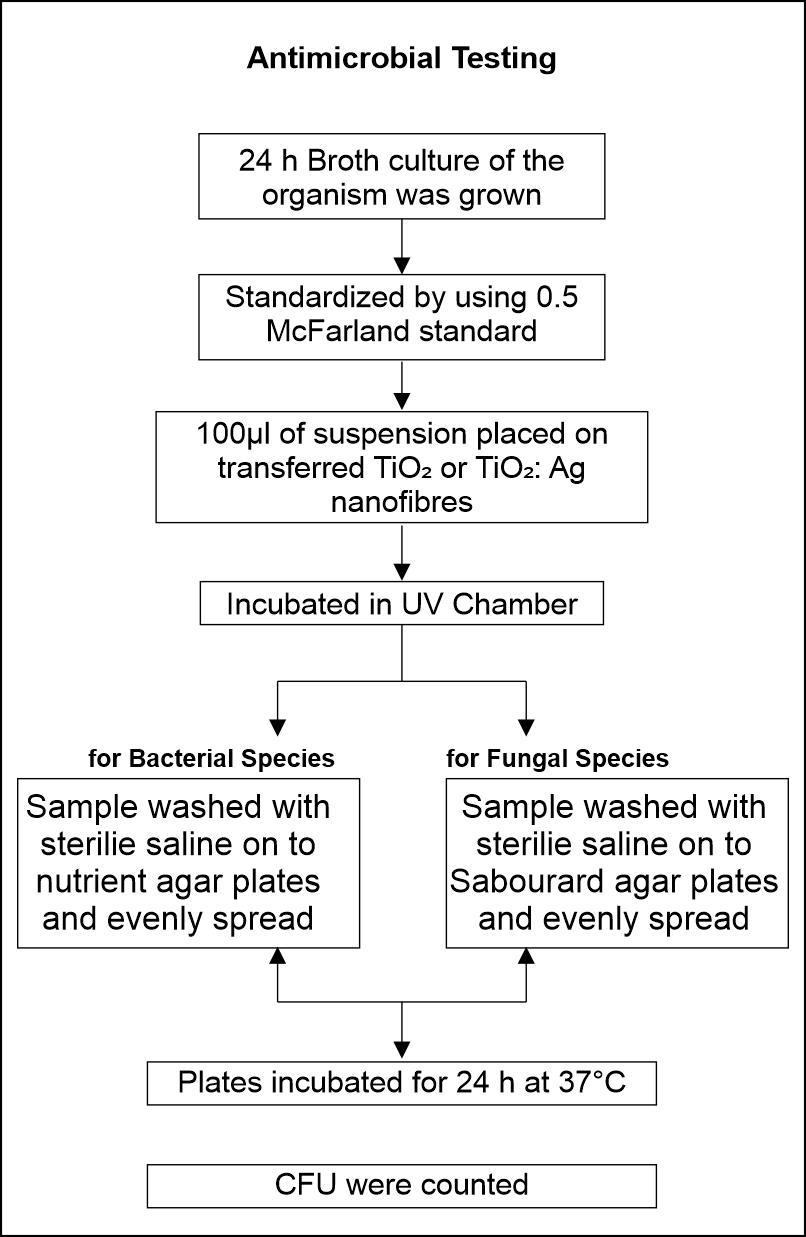
Fig. 1. Flowchart of antimicrobial testing
RESULTS AND DISCUSSIONS BY DROP TEST METHOD
Antimicrobial Tests for TiO2: Ag concentration
Anti bacterial Testing
The antibacterial testing was carried out for the following bacterial species: Bacillus subtilis (BS), Staphylococcus epidermidis (SE), Staphylococcus aureus (SA) and Staphylococcus faecalis (SF). Fig. 2 a and b is showing the results of Bacillus subtilis (BS) for TiO2: Ag. Fig. 2 c and d is showing the results of Staphylococcus epidermidis (SE) for TiO2: Ag.
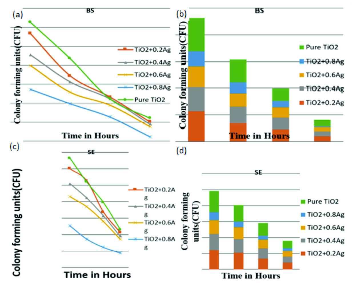
Fig. 2. (a) & (b):Bacillus subtilis (BS) for TiO2: Ag (a) & (b): Staphylococcus epidermidis (SE) for TiO2: Ag
Each tested bacterial species showed vulnerability to pure TiO2 and TiO2 – Ag nanofibers as shown in the figures. Fig. 2 a) and b) indicates antibacterial images of TiO2 +Ag at different concentrations on Staphylococcus aureus a) 0.2% Ag; b) 0.4% Ag. Fig. 2 b) and c) indicates antibacterial images of TiO2 +Ag at varying concentrations on Staphylococcus aureus c) 0.6% Ag; d) 0.8% Ag. There is an increase in susceptibility observed with increase in the concentration of Ag. At 0.8% Ag concentration Staphylococcus aureus shows drastic reduction of number of colonies formed with increase in Ag concentration and complete removal of organisms after 4 hours of exposure to UV. The other species show a gradual reduction in number of viable organisms with an increase in Ag concentration.
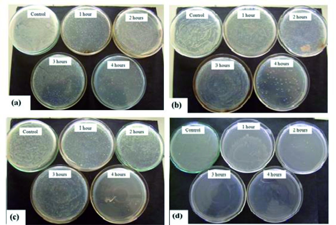
Fig. 3. Antibacterial Images of TiO2 +Ag at Different Concentrations on Staphylococcus aureus a) 0.2% Ag; b) 0.4% Ag c) 0.6% Ag; d) 0.8% Ag
SEM Analysis
The morphology of the obtained nanofibers was analyzed using SEM.
PVP Nanofibers
SEM images of PVP grown at distance 12cm and applied voltage between needle and substrate 12kV.
a) 15wt % PVP in ethanol deposited on Al foil at room temperature.
Fig. 4 a) indicates SEM image of 15% PVP Nanofibers under low magnification. Fig. 4 b) indicates SEM image of 15% PVP Nanofibers under high magnification.
b) 15wt % PVP in ethanol deposited on Al foil annealed at 200°C for 1 h in air ambient
Fig. 4 c) indicates SEM image of 15% PVP Nanofibers (200°C) under low magnification. Fig. 4 d) indicates SEM image of 15% PVP Nanofibers (200°C) under high magnification.
c) 15wt % PVP in ethanol deposited on Al foil annealed at 400°C for 1 h in air ambient
Fig. 4 e) indicates SEM image of 15% PVP Nanofibers (400°C) under low magnification. Fig. 5 f) indicates SEM image of 15% PVP Nanofibers (400°C) under high magnification.
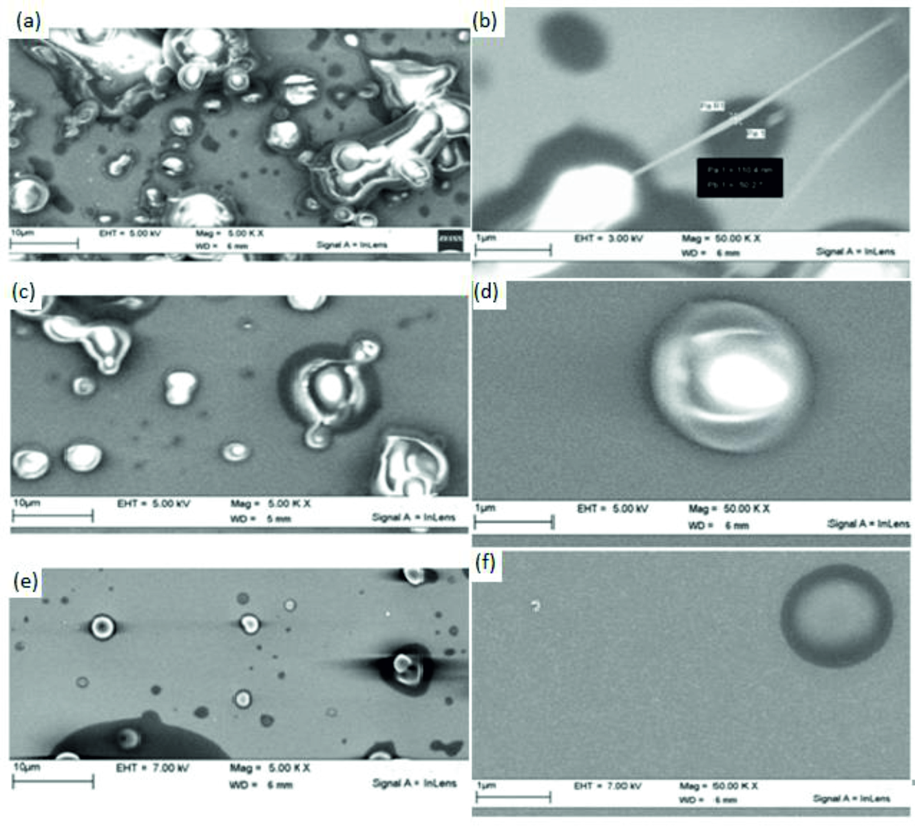
Fig. 4. SEM image of 15% PVP Nanofibers: a) Low Magnification, b) High Magnification, c) Low Magnification (200°C), d) High Magnification (200°C), e) Low Magnification (400°C), f) High Magnification (400°C).
At room temperature the nanofibers formed have an average diameter of 110.4nm diameter. On annealing at 200°C and 400°C for an hour the nanofibers get disintegrated. Hence for further experimentation 15% PVP in ethanol is taken as the optimized composition for PVP.
TiO2 – PVP Nanofibers
SEM images of TiO2: PVP grown at distance 12cm and applied voltage between needle and substrate 12kV.
a) TiO2: PVP with 5wt % TiO2 in ethanol deposited on Al foil at room temperature.
Fig. 5 a) indicates SEM image of 5% TiO2: PVP Nanofibers under low magnification. Fig. 5 b) indicates SEM image of 5% TiO2: PVP Nanofibers under high magnification.
b) TiO2: PVP with 10wt % TiO2in ethanol deposited on Al foil at room temperature
Fig. 5c) indicates SEM image of 10% TiO2: PVP Nanofibers under low magnification.
Fig. 5d) indicates SEM image of 10% TiO2: PVP Nanofibers under high magnification.
c) TiO2: PVP with 15wt % TiO2 in ethanol deposited on Al foil at room temperature.
Fig. 5 e) indicates SEM image of 15% TiO2: PVP Nanofibers under low magnification. Fig. 5 f) indicates SEM image of 15% TiO2: PVP Nanofibers under high magnification.
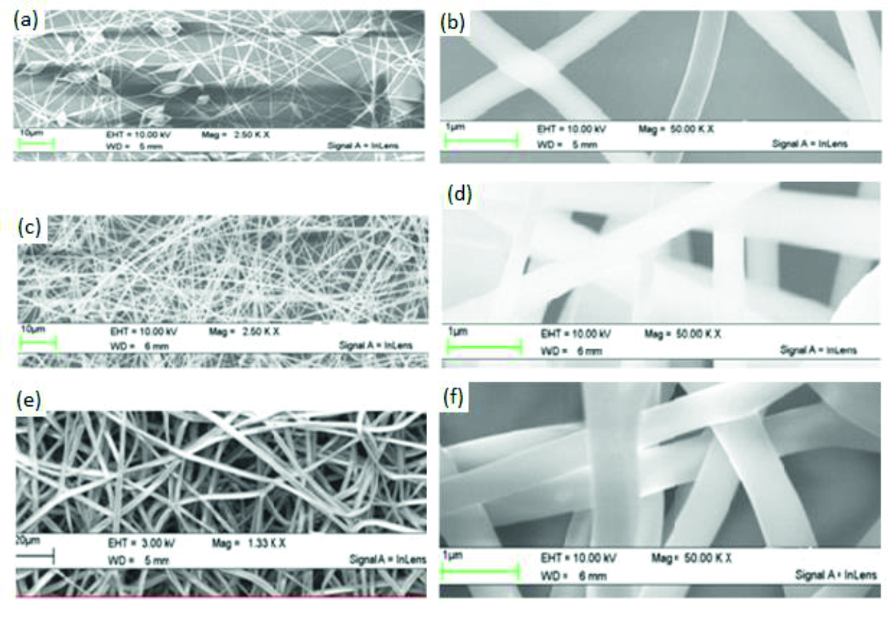
Fig. 5. SEM image of TiO2: PVP Nanofibers: a) Low Magnification (5% TiO2), b) High Magnification (5% TiO2), c) Low Magnification (10% TiO2) d) High Magnification (10% TiO2), e) Low Magnification (15% TiO2) f) High Magnification (15% TiO2).
TiO2: Ag Nanofibers
SEM images of TiO2: PVP: Ag grown at a distance of 10cm and applied voltage between needle and substrate 12kV.
a) 15wt% PVP in ethanol + 10wt% TiO2 + 0.2 wt% of Ag.
Fig. 6 a) indicates SEM image of 15% PVP: 10% TiO2: 0.2% Ag Nanofibers under low magnification Fig. 6 b) indicates SEM image of 15% PVP: 10% TiO2: 0.2% Ag Nanofibers under high magnification.
b) 15wt% PVP in ethanol + 10wt% TiO2 + 0.4 wt% of Ag.
Fig. 6 c) indicates SEM image of 15% PVP: 10% TiO2: 0.4% Ag Nanofibers under low magnification. Fig. 6 d) indicates SEM image of 15% PVP: 10% TiO2: 0.4% Ag Nanofibers under high magnification.
c) 15wt% PVP in ethanol + 10wt% TiO2 + 0.6 wt% of Ag
Fig. 6 e) indicates SEM image of 15% PVP: 10% TiO2: 0.6% Ag Nanofibers under low magnification. Fig. 6 f) indicates SEM image of 15% PVP: 10% TiO2: 0.6% Ag Nanofibers under high magnification.
d) 15wt% PVP in ethanol + 10wt% TiO2 + 0.8 wt% of Ag.
Fig. 6 g) indicates SEM image of 15% PVP: 10% TiO2: 0.8% Ag Nanofibers under low magnification. Fig. 6 h) indicates SEM image of 15% PVP: 10% TiO2: 0.8% Ag Nanofibers under high magnification.
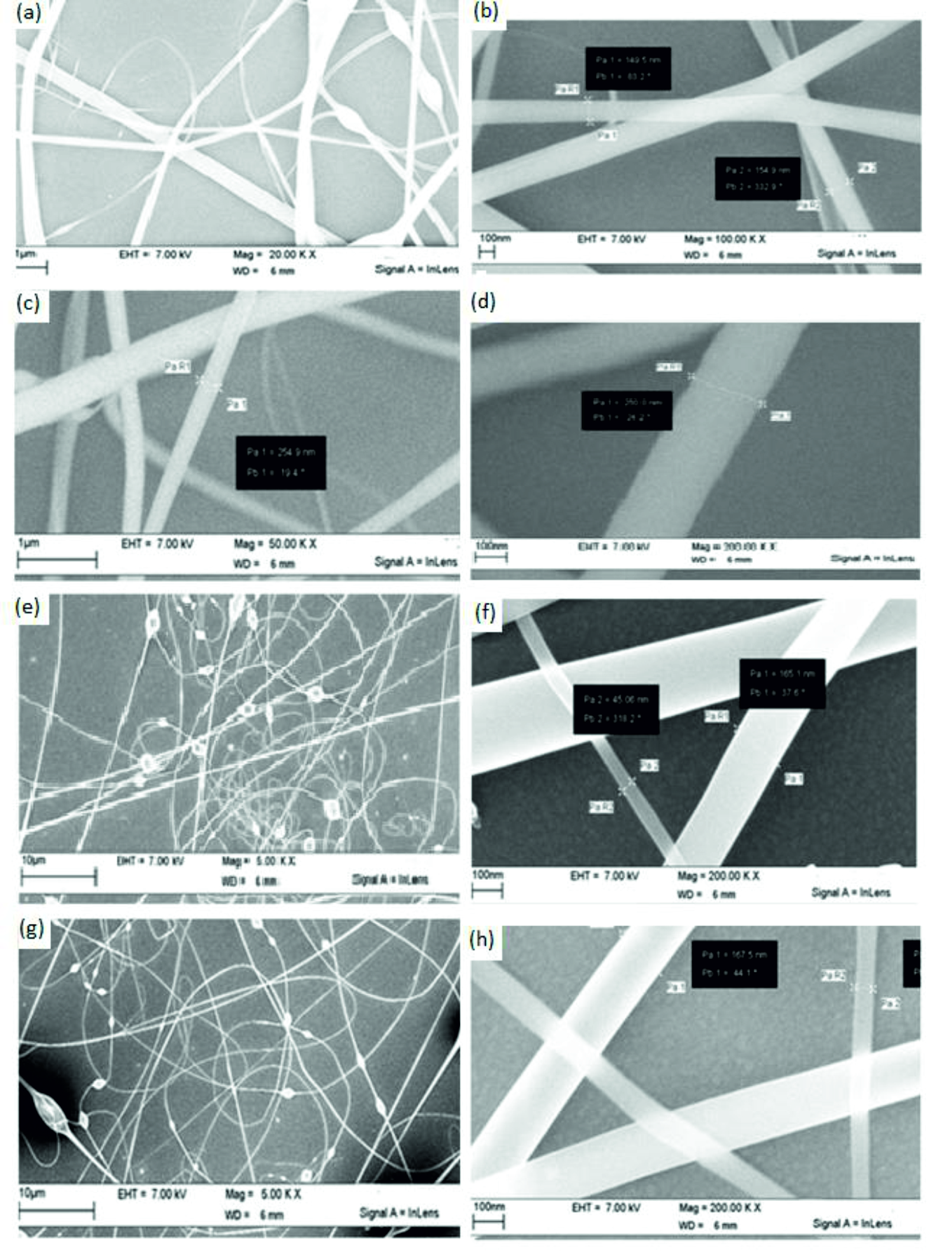
Fig. 6. SEM image of 15% PVP: 10% TiO2 : a) 0.2% Ag Nanofibers: Low Magnification, b) 0.2% Ag Nanofibers: High Magnification, c) 0.4% Ag Nanofibers: Low Magnification, d) High Magnification, e) 0.6% Ag Nanofibers: Low Magnification, f) 0.6% Ag Nanofibers: High Magnification, g) 0.8% Ag Nanofibers: Low Magnification, h) 0.8% Ag Nanofibers: High Magnification.
The nanofibers were obtained on varying the concentrations of silver as an additive to enhance the photocatalytic activity of base TiO2. Calculated quantity of the silver nitrate is taken in 50ml beaker and to it 2–methoxy ethanol solvent is added to make a homogenous solution. At 0.2 weight % of Ag the nanofibers had a diameter range of 145nm – 160nm. On increasing the weight % of silver to 0.4 the diameters of the nanofibers formed varied from 245nm to 260nm. However, on further increasing the silver concentration to 0.6 weight % and 0.8 weight % the diameters of the nanofibers varied approximately from 45nm to 170nm. The behavior of this change in diameter shrinkage is to be understood in detailed.
The nanofibers obtained were further tested for their antimicrobial properties for various bacterial and fungal species.
TiO2: Zn Nanofibers
The fibers grown with Zn as dopent with 0.2 wt % concentration have been shown in the Fig. 7. Images of the fibers shows with different magnification from lower right to top left. As can be seen from the Fig. 4.1 with lower magnification, we could see the formation of the fibers on the Al foil substrate. With slight increase in magnification we could see the twisting behavior of the nanofibers with one another. With further close observation of the nanofibers and measurement of the diameter using the software we could see the diameter of the fiber is around 2.3 microns. However, in some area we could see the diameter of the fiber is as low as 650 nm as shown in the top left image in Fig. 7.
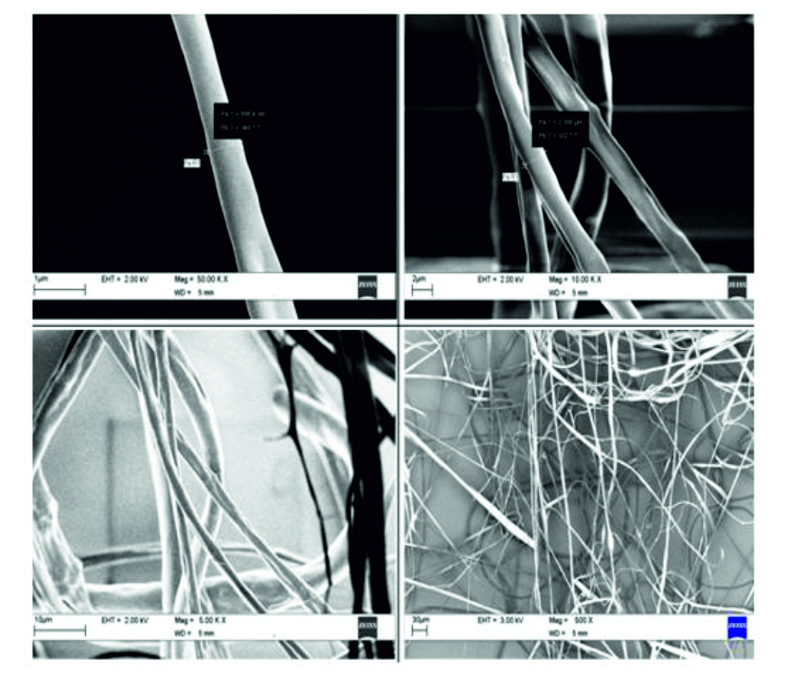
Fig. 7. SEM image of 15% PVP: 10% TiO2: 0.2% Zn nanofibers.
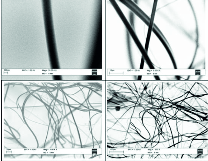
Fig 8: SEM image of 15% PVP: 10% TiO2: 0.4% Zn nanofibers.
The fibers grown with Zn as dopent with 0.4 wt % concentration have been shown in the Fig. 8. Images of the fibers shows with different magnification from lower right to top left. As can be seen from the right side Fig. 8, with lower magnification, we could see the formation of the fibers on the Al foil substrate with almost high uniformity. With slight increase in magnification we could see the twisting behavior of the nanofibers with one another. With further close observation of the nanofibers and measurement of the diameter using the software we could see the diameter of the fiber is nearly 1.7 microns. However, in some area we could see the diameter of the fiber is as low as 230 nm as shown in the top left image in Fig. 8.
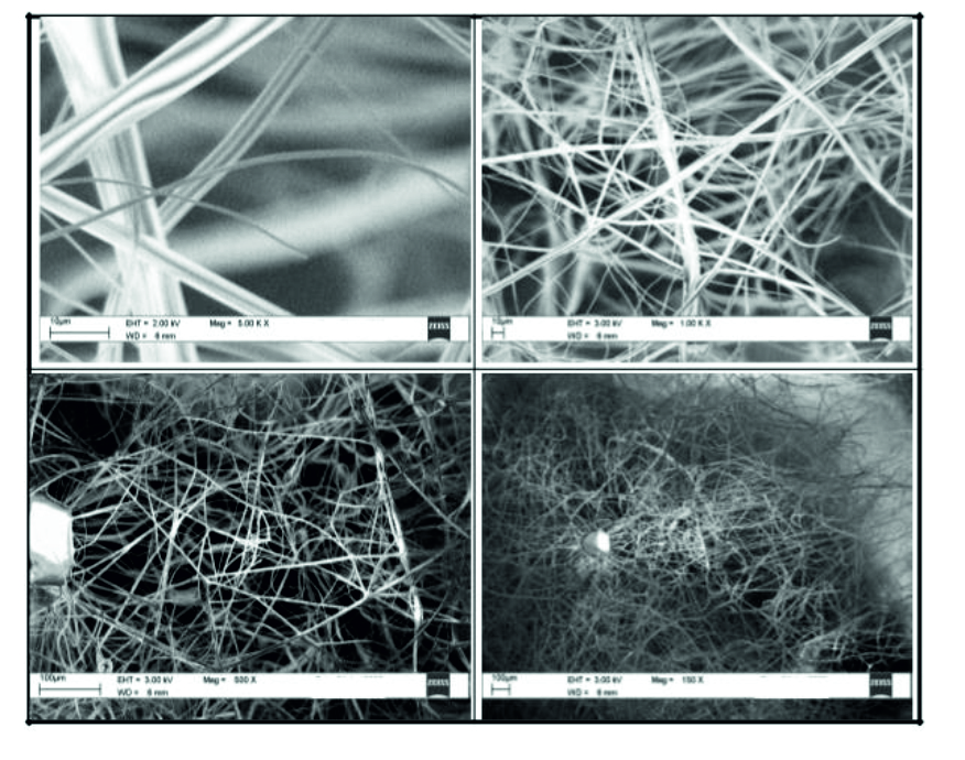
Fig. 9. SEM image of 15% PVP: 10% TiO2: 0.6% Zn nanofibers.
The fibers grown with Zn as dopent with 0.4 wt % concentration have been shown in the Fig. 9. Images of the fibers shows with different magnification from lower right to top left. As can be seen from the Fig. 9 with lower magnification, we could see the formation of the fibers on the Al foil substrate with almost high uniformity. With slight increase in magnification we could see the twisting behavior of the nanofibers with one another and with two to three different diameters of the nanofibers. With further close observation of the nanofibers and measurement of the diameter using the software we could see the diameter of the fiber is around 1.9 microns. However, in some area we could see the diameter of the fiber is as low as 530 nm as shown in the top left image in Fig. 9.

Fig. 10. SEM image of 15% PVP: 10% TiO2: 0.8% Zn nanofibers.
The fibers grown with Zn as dopent with 0.4 wt % concentration have been shown in the Fig. 10. Images of the fibers shows with different magnification from lower right to top left. As can be seen from the Fig. 10 with lower magnification, we could see the formation of the fibers on the Al foil substrate with almost high uniformity. With slight increase in magnification we could see the twisting behavior of the nanofibers with one another and with two to three different diameters of the nanofibers. With further close observation of the nanofibers and measurement of the diameter using the software we could see the diameter of the fiber is around 2.1 microns. However, in some area we could see the diameter of the fiber is as low as 430 nm as shown in the top left image in Fig. 10.
The composition of PVP nanofibers were optimized at a concentration of 15 weight % in ethanol. The optimized composition was further used to synthesize TiO2: PVP nanofibers. Titanium dioxide: PVP nanofibers were synthesized at varying concentrations. TiO2: PVP with 10wt % TiO2 in ethanol was chosen as the optimized condition. TiO2: PVP with 15wt % TiO2 in ethanol was chosen as the optimized condition. Nanofibers of TiO2: PVP doped with Ag were obtained using varying Ag concentrations. Nanofibers of TiO2: PVP doped with Ag were obtained using varying Zn concentrations. The morphology of the obtained nanofibers was analyzed by Scanning Electron Microscopy (SEM), Fourier Transform Infra Red radiation (FTIR) and X-ray Diffraction (XRD). The anti bacterial testing was carried out on the following bacterial species; Bacillus subtilis (BS), Staphylococcus epidermidis (SE), Staphylococcus aureus (SA) and Staphylococcus faecalis (SF).The anti fungal testing was carried out on the following species; Candida tropicalis(CT), Candida parapsilosis (CP), Candida albicans (CA) and Candida glabrata (CG).
ACKNOWLEDGEMENTS
The authors listed in this paper wish to express their appreciation to the RSST trust Bangalore and Department of Biochemistry, Maharani’s Science College for women, Bangalore for their continuous support and encouragement. As a corresponding author, I also express my sincere thanks to all other authors whose valuable contribution and important comments made this manuscript to this form.
CONFLICT OF INTEREST
The authors declare that there is no conflict of interest.
AUTHORS’ CONTRIBUTION
All authors have made substantial contribution to the work and approved it for publication.
FUNDING
None.
DATA AVAILABILITY
All datasets generated or analyzed during this study are included in the manuscript.
ETHICS STATEMENT
This article does not contain any studies with human participants or animals performed by any of the authors.
- Huang, Zheng-Ming, M. Kotak and S. Ramakrishna. “A review on polymer nanofibers by electrospinning and their applications in nanocomposites”. Composites Science and Technology, 2003; 63(15): 2223-2253.
Crossref - Abdel-Ghani MS, Davies GA. “Simulation of non-woven fiber mats and the application to coalescers”. Chemical Engineering Science, 1985; 40(1): 117, p 29.
Crossref - Baughman RH, Zakhidov AA, de Heer WA. Carbon nanotubes—the route toward applications. Science, 2002; 297: 787 p 92.
Crossref - Adanur S and Liao T. “Computer simulation of mechanical properties of nonwoven geotextiles in soil-fabric interaction”. Textile Res. J., 1998; 68: 155: p.62.
Crossref - Taylor GI. “Electrically driven jets”. Proc. R. Soc. London, Ser. A., 1969; 313: 453, p.75.
Crossref - Suresh L. shenoy, W. Douglas, Harry, Frisch, Gary and Wnek. “Role of chain entanglements on fiber formation during electrospinning of polymer solutions: good solvent, non-specific polymer–polymer interaction limit”. Polymer, 2005; 46(10): pp. 3372-3384.
Crossref - Fong, Chun and D.H. Reneker. “Beaded nanofibers formed during electrospinning”. Polymer, 1999; 40(16): pp. 4585-4592.
Crossref - Chand, S. “Review carbon fibers for composites”. Journal of Materials Science, 2000; 35(6): pp. 1303-1313.
Crossref - Lee, Sung-Hwan, Cagri Tekmen, and Wolfgang M. Sigmund. “Three-point bending of electrospun TiO2 nanofibers”. Materials Science and Engineering: A, 2005; 398(1): pp. 77-81.
Crossref - Sudha Madhugiri, Bo Sun, Panagiotis G. Smirniotis, John P. Ferraris and Kenneth J. Balkus Jr. “Electrospun mesoporous titanium dioxide fibers”, Microporous and Mesoporous Materials, 2004; 69(1): pp. 77-83.
Crossref - Chandrasekar Ramya. “Fabrication and characterization of electrospun titania nanofibers”, Journal of Materials Science, 2009; 45(5): pp. 1198-1205.
Crossref - Ming Jin, Xintong Zhang, Shunsuke Nishimoto, Zhaoyue Liu, Donald A. Tryk, Alexei V.Emeline, Taketoshi Murakami, and Akira Fujishima”. Light stimulated composition conversion in TiO2-based nanofibers”. The Journal of Physical Chemistry C., 2007; 111(2): pp. 658-665.
Crossref - Kim, Mi-Ra, Ji-Un Kim and Lee. “New application of electrospun TiO2 electrode to solid- state dye-sensitized solar cells”. Synthetic Metals, 2005; 153: pp. 77–80.
Crossref - Matsunaga Tadashi, Hitoshi Wake, Ryozo Tomoda and Toshiaki Nakajima. “Photoelectrochemical sterilization of microbial cells by semiconductor powders”. FEMS Microbiology Letters, 1985; 29(1): pp. 211-214.
Crossref - Byunghoon Kim, Dohwan Kim, Donglyun Cho and Sungyong Cho. “Bactericidal effect of TiO2 photocatalyst on selected food-borne pathogenic bacteria”. Chemosphere, 2003; 52(1): pp.277-281.
Crossref - Stoimenov, Peter K., and Kenneth J. Klabunde. “Nanotechnology in biological agent decontamination”. Nanofabrication Towards Biomedical Applications: Techniques, Tools, Applications and Impact, 2005; pp. 365-372.
Crossref - Wu, Pinggui, Jian and Xie. “Monolithic ceramic foams for ultrafast photocatalytic inactivation of bacteria”. Journal of the American Ceramic Society, 2009; 92(8): pp. 1648-1654.
Crossref - Pinggui Wu, Xie and Jian. “Visible-light-induced photocatalytic inactivation of bacteria by composite photocatalysts of palladium oxide and nitrogen-doped titanium oxide”, Applied Catalysis B: Environmental, 2009; 88(3): pp. 576-581.
Crossref - Kaneko, Masao, and Ichiro Okura. “Photocatalysis Science and Technology”. Kodansha Springer, 2002.
- Pinggui Wu, Rongcai Xie, and Jian Ku Shang. “Enhanced Visible_Light Photocatalytic Disinfection of Bacterial Spores by Palladium_Modified Nitrogen_Doped Titanium Oxide”, Journal of the American Ceramic Society, 2008; 91(9): pp. 2957-2962.
Crossref - Vohra, Goswami, Deshpande and Amit. “Enhanced photocatalytic inactivation of bacterial spores on surfaces in air”, Journal of Industrial Microbiology and Biotechnology, 2005; 32(8): pp. 364-370.
Crossref - Wolfrum, Edward J, Blake, Maness, Huang, Fiest and Jacoby. “Photocatalytic oxidation of bacteria, bacterial and fungal spores, and model biofilm components to carbon dioxide on titanium dioxide-coated surfaces”, Environmental Science & Technology, 2002; 36(15): pp. 3412-3419.
Crossref - Li Qi, Xie, Mintz and Shang. “Enhanced Visible_Light Photocatalytic Degradation of Humic Acid by Palladium_Modified Nitrogen_Doped Titanium Oxide”, Journal of the American Ceramic Society, 2007; 90(12): pp. 3863-3868.
- Xu Jie, Shang, Gao, Ren and Zhang. “Electrospun nanofibers of Bi-doped TiO2 with high photocatalytic activity under visible light irradiation”, Journal of Hazardous Materials, 2011; 196: pp. 426-430.
Crossref - Jeong, Eun Hwan, Jie Yang, and Ji Ho Youk. “Preparation of polyurethane cationomer nanofiber mats for use in antimicrobial nanofilter applications”, Materials Letters, 2007; 61(18): pp. 3991-3994.
Crossref - Lala, Neeta L, Ramaseshan, Bojun, Sundarrajan, Barhate and Ramakrishna. “Fabrication of nanofibers with antimicrobial functionality used as filters: protection against bacterial contaminants”, Biotechnology and Bioengineering, 2007; 97(6): pp. 1357-1365.
Crossref - Liu, Xin, Lin, Fang, Yao and Wang. “In vivo wound healing and antibacterial performances of electrospun nanofiber membranes”, Journal of Biomedical Materials Research Part A, 2010; 94(2): pp. 499-508.
- Kong, Hyeyoung, and Jyongsik Jang. “Synthesis and antimicrobial properties of novel silver/polyrhodanine nanofibers”, Biomacromolecules, 2008; 9(10): pp. 2677- 2681.
Crossref - Sheikh A. Faheem, Nasser A.M. Barakat, Muzafar, Lee, Atul A. chaudhari and Hak Yong Kim. “Electrospun antimicrobial polyurethane nanofibers containing silver nanoparticles for biotechnological applications”, Macromolecular Research, 2009; 17(9): pp. 688-696.
Crossref - Byung-Yong Lee, Kris Behler, Murat Erdem Kurtoglu, Meghan Ann Wynosky- Dolfi ,Richard F. Rest and Yury Gogotsi. “Titanium dioxide-coated nanofibers for advanced filters”, J. Nanopart Res., 2010; 12: pp.2511–2519.
Crossref - Kristine Graham, Ming Ouyang, Tom Raether, Tim Grafe, Bruce McDonald and Paul Knauf Donaldson. “Polymeric Nanofibers in Air Filtration Applications”. Presented at the Fifteenth Annual Technical Conference & Expo of the American Filtration & Separations Society, Galveston, Texas, April 9-12, 2002.
- Reneker D.H. and Chun I., “Nanometer Diameter Fibers of Polymer, Produced by Electrospinning”, Nanotechnology, 1996; 7: pages 216-233.
Crossref - Grafe T.H., Gogins, M., Barris M.A., Schaefer J., Canepa R., “Nanofibers in Filtration Applications in Transportation”, Filtration 2001 Conference Proceedings, 2001.
- Won Keun Son, Ji Ho Youk and Won Ho Park. “Antimcrobial cellulose acetate nanofibers containing silver nanoparticles”. Science Direct, Carbohydrate polymers, 2006; 65: pp.430-434
Crossref - Dr. Ahmad A., Gul Hameed Awan and Salman Aziz. “Synthesis and applications of TiO2 nanoparticles”, 2013.
- Prassas M. and Hench L.L. “Ultrastructure Processing of Ceramics, Glasses, and Composite”. (John Wiley & Sons :New York, 1984), pp. 100-125.
- Brinker C.J. “Non-Crystalline Solids”. 1988; 100: pp. 31-50.
Crossref - Brinker C.J., Clark D.E., and Ullrich D.R., Sakka. “Better Ceramics Through Chemistry “. Elsevier-North Holland: New York, 1984: p. 91.
- Strober W., Fink A. and Bohn E.J. “Colloid Interface” Science Direct, 1968; 26: pp. 62-69.
Crossref - Jiang C.Y. and Mark J.E. Makromol. Chem., 1984; 185: pp 2609-2613.
Crossref - Zerda. T.W., Artaki.I and Jonas J.J. “Non Crystalline Solids”. 1986; 81: pp. 374-376.
Crossref - Sakka.S and Kamiya.K.J. “Non-Crystalline Solids”. 1982; 48: p. 31.
Crossref - Brinker C.J. and. Scherer. G.W. “Non Crystalline Solids”, 1985; 70: pp.301 322.
Crossref - Bragg W.L., “The Diffraction of Short Electromagnetic Waves by a Crystal”, Proceedings of the Cambridge Philosophical Society, 1913; 17: pp. 43–57.
- Umemura J., Kamata , Kawai T., Takenaka T. “Quantitative evaluation of molecular orientation in thin Langmuir-Blodgett films by FT-IR transmission and reflection absorption spectroscopy”. J. Phys. Chem., 1990; 94 (1): pp 62–67.
Crossref - Jung Woo Kim, Dongwoo Kang, Tae Hyeong Kim, Sung Guk Lee, Nami Byun, Dong Wook Lee, Byung Hwa Seo, Rodney S. Ruoff, and Hyeon Suk Shin “ACS Nano”, 2013; 7(9): pp. 8082-8088.
Crossref - Elena Madrid and Sarah L. Horswell. “Langmuir”. 2013; 29(5): pp.1695-1708.
Crossref - Thio B.J.R., Zhou and Keller D., Influence of natural organic matter on the aggregation and deposition of titanium dioxide nanoparticles. J. Hazard. Mater., 2011;
Crossref - Byung-Ok Jung, Chun-Ho Kim, Kyu-Suk Choi, Young Moo Lee and Jae-Jin Kim. “Preparation of amphiphilic chitosan and their antimicrobial activities”, J. Appl. Polym. Sci., 72: pp.1713–1719.
Crossref - Sun Hye Hwang, Jooyoung Song, Yujung Jung, O Young Kweon, Hee Song and Jyongsik Jang. “Electrospun ZnO/TiO2 Composite Nanofibers as a Bactericidal Agent”. Electronic Supplementary Material (ESI) for Chemical Communications, Royal Society of Chemistry 2014.
© The Author(s) 2019. Open Access. This article is distributed under the terms of the Creative Commons Attribution 4.0 International License which permits unrestricted use, sharing, distribution, and reproduction in any medium, provided you give appropriate credit to the original author(s) and the source, provide a link to the Creative Commons license, and indicate if changes were made.