ISSN: 0973-7510
E-ISSN: 2581-690X
The objective of this in vitro study was to evaluate and compare the marginal and internal gaps of full contour zirconia crowns using three different digital intra-oral scanners with different software design. Samples were distributed into five groups eight for each according to the type of scanner and software design used during milling procedure as follows: Group A: CEREC Omnicom + InLab SW 16.1. Group B: TRIOS3 + software of 3Shape dental system. Group C: TRIOS3 + InLab SW 16.1. Group D: CS3600 + software of exocad program. Group E: CS3600 + InLab SW 16.1. The crowns of all groups were milled with the same milling machine inLab MCX5. The marginal and internal fitness of crown was evaluated by direct measurement of cement thickness through sectioning procedure. The data were then analyzed using One-way ANOVA test and Tukey’s (HSD) test. The results of this study showed that the least marginal gap was recorded in Group C (59.038, ±9.667) followed by Group D (63.405, ±6.038), Group E (64.674, ±6.478), Group B (70.112, ±4.954) and Group A (81.703, ±7.428) respectively. While for the internal gap, the least internal gap was recorded at Group C and Group B (119.691, ±4.107), (119.192, ±4.068) respectively followed by Group A (123.254, ±6.777), Group D (123.485, ±5.353) and Group E (130.816, ±3.926). As a conclusion, the intra-oral scanner that provides more accurate seating of monolithic crown restoration was TRIOS3.
Intraoral scanner, Digital impression, STL datasets, CAD/CAM, All ceramic restoration, marginal fitness, internal fitness
The Marginal and internal fitness play an important role in the longevity of crown restoration. A number of factors might affect this fitness such as: preparation design, location of the margin (supra or subgingival), quality of milling device, milling bur, cement spacer and image capturing system1, 2, 3. In the fabrication of a prosthesis using a CAD-CAM workflow, long term success depends on the system involved in scanning the tooth surface and in prosthesis design which determine the marginal and internal fit of the restoration to the abutment tooth4.
The scanning of the recommended area for reconstruction is done with intra-oral scanner instead of conventional impression that enormously contributes to easier workflow and assists in preparation and cementation of crown in one session2, 5. The advancement of intra-oral cameras for high precision scanning, sophisticated software and milling standardization has reduced the marginal and internal discrepancy of crowns fabricated by CAD-CAM systems2. Modeling and milling depends mainly on the data acquired from the optical impression, so the use of most precise intra-oral scanners would be favorable to improve the quality of internal and marginal adaptation of restorations6.
Digital work helps in better restoration fitness because the scanned teeth can be magnified greatly and allows better restoration design besides that any area look to be insufficiently reproduced can be re-examined and rescanned2, 5.
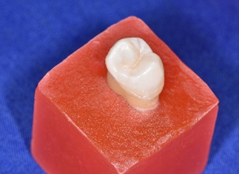
Forty sound human maxillary first premolar teeth of comparable size and shape extracted for orthodontic purpose from patient age (18-24) years were selected and collected in this study. Only sound teeth which are free from caries, cracks and enamel defects were selected7. The teeth were stored in deionized distilled water to keep them hydrated during all stages of the study8. All teeth were embedded in cold cure acrylic resin (Fig.1) 2mm below cemento-enamel junction according to the level of supporting alveolar bone7.

Fig. 1. Tooth sample
All teeth were prepared to receive monolithic zirconia crown, the preparation was done by one operator to avoid inter-examiner differences9. Tooth preparation was done with aid of modified dental surveyor to which high speed hand-piece with water/air coolant was adapted to its’ horizontal arm in such away so that bur will be kept parallel to the long axis of the tooth during axial wall preparation. A horizontal table (movable) was used to secure the acrylic block to ensure that long axis of tooth will be parallel to the bure and maintain the same convergence angle of preparation10. Teeth were then prepared for all ceramic restoration following the guidelines recommended for inCoris TZI C with the following features: (planner occlusal reduction, axial reduction 1mm-1.5mm, deep chamfer finishing line 0.8mm in depth, 60 convergence angle, and 4mm occluso-gingival height), these preparations were made by rugby ball bur (NO. 804647), round end tapered fissure bur (NO. 903319) for preparation and (NO. 931749) for finishing.
All fabrication procedures including model scanning, software designing, milling and sintering protocols were done according to the manufacturer instruction of zirconia (inCoris TZI C) and CAD-CAM milling system used. For the purpose of standardization a single scanning protocol was applied to all the three types of scanners, and a three dimensional digital model was produced and exported as STL file image.
The latest versions of intraoral scanners (CEREC Omnicam, Trios3, CS3600) were selected for this study, since in digital dentistry modeling and milling depend essentially on the data acquired through the optical impression. Sirona InLab software 16.1, 3Shape design software and exocad were used to designate crown restoration. In order to standardize the dimension and shape of final crown restoration for all specimens, one crown was considered as a reference for all the other groups and the fabricated crown was scanned and used to design the other monolithic crowns11.
The crowns of all groups were milled by the same milling machine MCX5 (Sirona, Germany). The design of all groups was exported to CAM inLab SW16.1. The crowns after milling procedure were sintered into inFire HTC speed furnace (Sirona, Germany). Custom made holding and cementation device was used in this study to secure zirconia crown on natural tooth sample and to maintain seating force during cementation procedure12. A modification was added to this device, this modification allows more accurate seating of crown restoration for all specimens by allowing single standardized direction of applied load (5kg) that is perpendicular to the occlusal surface of crown restoration during cementation.
In this study, the fitness of crown was evaluated by direct measurement of cement thickness through sectioning procedure which is very beneficial tool that helps to reduce chance of software and repositioning error13, and allow uninterrupted view of the gap14. This procedure require embedding of tooth sample in acrylic resin to reduce chance of sample destruction15.
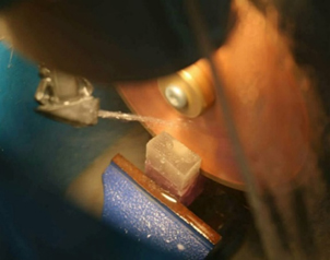
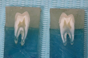
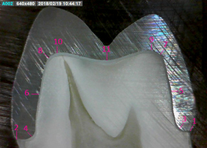
In order to make standardized cutting area through the specimen during sectioning procedure, a single seating position was chosen in sectioning machine for all specimens. A suctioning blade of 0.3mm thickness was used (Fig. 2, 3, 4). A digital microscope was used to measure the cement space between the zirconia crown and tooth at predetermined points. The magnification of 230X was used in this study because it was large enough to view the marginal and internal gap accurately. Eleven different predetermined measuring points were selected for each sample, these points indicate the four measuring different areas: (two marginal, two chamfer, four axial, three occlusal) (Fig. 5).

Fig. 2. The beginning of sectioning procedure

Fig. 3. Sectioning of tooth sample with efficient water coolant

Fig. 4. The two sections (mesial and distal) after completion of sectioning procedure

Fig. 5. Microscopical image at low magnification (30x) showing the measuring points of Bucco-palatal section
Descriptive statistics of the gap at the different areas of the five different groups measured in ¼m were listed in Table 1. The highest mean value of the gap was recorded at the occlusal area (170.652, ±8.579) of Group D, while the lowest mean value of the gap was recorded at the marginal area (59.038, ±9.667) of Group C. Table 2 the table also showed that in general, the lowest marginal and internal gaps (59.038, ±9.667) (119.691, ±4.107) was recorded at Group C while the highest marginal gap (81.703, ±7.428) was recorded in Group A and the highest internal gap (130.816, ±3.926) was recorded in Group E.
Table (1):
Descriptive statistics of the gap at the different areas of the five different groups measured in µm
| Groups | Areas | N | Mean | S.D. | Min. | Max. |
|---|---|---|---|---|---|---|
| Group
A |
Marginal | 8 | 81.703 | 7.428 | 73.913 | 95.652 |
| Chamfer | 8 | 136.299 | 8.501 | 121.957 | 147.570 | |
| Axial | 8 | 90.117 | 6.043 | 79.710 | 96.377 | |
| Occlusal | 8 | 143.347 | 10.408 | 134.198 | 156.521 | |
| Internal | 8 | 123.254 | 6.777 | 115.611 | 131.779 | |
| Group
B |
Marginal | 8 | 70.112 | 4.954 | 62.319 | 75.362 |
| Chamfer | 8 | 93.898 | 4.382 | 88.130 | 102.480 | |
| Axial | 8 | 100.274 | 6.221 | 90.580 | 107.250 | |
| Occlusal | 8 | 163.406 | 5.943 | 153.620 | 169.080 | |
| Internal | 8 | 119.192 | 4.068 | 112.826 | 124.336 | |
| Group
C |
Marginal | 8 | 59.038 | 9.667 | 47.826 | 71.014 |
| Chamfer | 8 | 113.178 | 5.624 | 102.479 | 120.925 | |
| Axial | 8 | 91.298 | 5.368 | 81.884 | 96.376 | |
| Occlusal | 8 | 154.597 | 7.386 | 144.927 | 165.217 | |
| Internal | 8 | 119.691 | 4.107 | 113.862 | 125.666 | |
| Group
D |
Marginal | 8 | 63.405 | 6.038 | 50.724 | 69.565 |
| Chamfer | 8 | 92.231 | 5.586 | 84.033 | 98.380 | |
| Axial | 8 | 107.572 | 5.515 | 100.000 | 115.942 | |
| Occlusal | 8 | 170.652 | 8.579 | 159.420 | 183.575 | |
| Internal | 8 | 123.485 | 5.353 | 115.772 | 130.099 | |
| Group E | Marginal | 8 | 64.674 | 6.478 | 53.623 | 69.565 |
| Chamfer | 8 | 149.363 | 6.239 | 141.421 | 157.818 | |
| Axial | 8 | 89.221 | 9.795 | 74.637 | 100.000 | |
| Occlusal | 8 | 153.864 | 9.392 | 143.961 | 168.115 | |
| Internal | 8 | 130.816 | 3.926 | 124.837 | 134.853 |
Table (2):
One-way ANOVA test for comparison of the gap among the different areas of each group
| Groups | ANOVA | Sum of Squares | d.f. | Mean Square | F-test | p-value |
|---|---|---|---|---|---|---|
| Group
A |
Between Groups | 23734.687 | 3 | 7911.562 | 116.231 | 0.000
(HS) |
| Within Groups | 1905.892 | 28 | 68.068 | |||
| Total | 25640.579 | 31 | ||||
| Group
B |
Between Groups | 38074.267 | 3 | 12691.422 | 431.094 | 0.000
(HS) |
| Within Groups | 824.320 | 28 | 29.440 | |||
| Total | 38898.588 | 31 | ||||
| Group
C |
Between Groups | 38608.882 | 3 | 12869.627 | 246.946 | 0.000
(HS) |
| Within Groups | 1459.227 | 28 | 52.115 | |||
| Total | 40068.109 | 31 | ||||
| Group
D |
Between Groups | 49295.309 | 3 | 16431.770 | 382.860 | 0.000
(HS) |
| Within Groups | 1201.719 | 28 | 42.919 | |||
| Total | 50497.027 | 31 | ||||
| Group
E |
Between Groups | 47092.224 | 3 | 15697.408 | 236.898 | 0.000
(HS) |
| Within Groups | 1855.343 | 28 | 66.262 | |||
| Total | 48947.567 | 31 |
One-way ANOVA test was used for comparison of the gap among the different areas of each group as listed in Table2, inn which there is a statistically highly significant difference of the gap among the different areas of each group (P Value <0.01).
The quality of prosthetic restorations is ensured through the exactness of internal and marginal fit. CAD-CAM technology has allowed fabrication of more precise ceramic crowns than conventional methods. Marginal and internal fitness of CAD-CAM restoration will depend on the quality of 3-dimentional (3D) image. The important part in the planning of a prosthesis is making an accurate virtual cast of the prepared tooth16.
When comparing the marginal and internal fitness of monolithic zirconia crowns using three different intra-oral scanners and single design software the results revealed that the lowest marginal gap was recorded in Group C (Trios3) (59.038, ±9.667) followed by Group E (CS3600) (64.674, ±6.478) and Group A (Omnicam) (81.703, ±7.428). While the internal gap Group C (Trios3) recorded (119.691, ±4.107) followed by Group A (Omnicam) (123.254, ±6.777) and Group E (CS3600) (130.816, ±3.926). However when comparing the marginal and internal fitness of monolithic zirconia crowns using different software design (Sirona inLab SW16.1, 3shape dental system, exocad), the results revealed that the lowest marginal gap was recorded in Group D (CS3600) (63.405, ±6.038) followed by Group B (Trios3) (70.112, ±4.954) and Group A (Omnicam) (81.703, +-7.428). While the lowest internal gap was recorded in Group B (Trios3) (119.192, ±4.068) followed by Group A (Omnicam) (123.254, ±6.777) and Group D (CS3600) (123.485, ±5.353), these findings may be contributed to:
- The different working principles (technological aspect) used by various intra-oral scanners could lead to different scan precision17. Trios3 system works with concept of ultrafast optical sectioning and confocal microscopy, in which the variations in the focus plane are recognized by the system16, 18, 19. Carestream 3600 system works according to the principle of active 3D video, it is LED light scanner6. CEREC Omnicam works with active triangulation technique and emits white light of different wavelength that focused on the same point. If the surface presents an uneven light dispersion it might decrease the scanning accuracy16, 18, 19.
- All scans were exported as STL files, in this file format a scanned surface is approximated using triangle from the point cloud generated by 3Dscanner. Scanners with high-definition sensors generated more points and a shorter point to point distance thus producing more triangles for surface reconstruction that would result in a more detailed representation of the scanned body. The Trios3 had the lowest number of triangles20.
- The physical resolution of the scanning system and further the post processing of the data21.
- The fit of restoration was influenced by the quality of design program, by the translation of the design code into the numerically controlled milling process and by the quality of the milling device themselves (the use of small bur diameters and higher degree of freedom of milling axis lead to smaller gap) 22.
The above findings were in agreement with Gray D. and Sebastian B (2015), Bohner et al. (2017), Carbajal Mejia et al. (2017), kocaagaoglu et al. (2017), Nedelcu et al. (2018)7, 16, 18, 20, 23.
As a conclusion, the intra-oral scanner that provides more accurate seating of monolithic crown restoration is TRIOS3.
- Boeddinghaus, Moritz, et al. “Accuracy of single-tooth restorations based on intraoral digital and conventional impressions in patients.” Clinical oral investigations, 2015; 19(8): 2027-2034.
- De Paula Silveira, Alessandra C., et al. “Marginal and internal fit of CAD-CAM-fabricated composite resin and ceramic crowns scanned by 2 intraoral cameras.” Journal of Prosthetic Dentistry, 2017; 117(3): 386-392.
- Shamseddine, Loubna, et al. “Marginal and internal fit of pressed ceramic crowns made from conventional and computer-aided design and computer-aided manufacturing wax patterns: An in vitro comparison.” Journal of Prosthetic Dentistry, 2016; 116(2): 242-248.
- Shimizu, Sakura, et al. “The accuracy of the CAD system using intraoral and extraoral scanners for designing of fixed dental prostheses.” Dental materials journal, 2017; 36(4): 402-407.
- Neves, Flávio D., et al. “Micro-computed tomography evaluation of marginal fit of lithium disilicate crowns fabricated by using chairside CAD/CAM systems or the heat-pressing technique.” Journal of Prosthetic Dentistry, 2014; 112(5): 1134-1140.
- Imburgia, Mario, et al. “Accuracy of four intraoral scanners in oral implantology: a comparative in vitro study.” BMC oral health, 2017; 17(1): 92.
- Kocaaaolu, Hasan, Halil Ibrahim K1l1nç, and Haydar Albayrak. “Effect of digital impressions and production protocols on the adaptation of zirconia copings.” Journal of Prosthetic Dentistry, 2017; 117(1): 102-108.
- Abdo, Salma B., et al. “Fracture resistance of over-flared root canals filled with MTA and resin-based material: an in vitro study.” Brazilian Journal of Oral Sciences, 2012; 11(4): 451-457.
- Sakornwimon, Nawapat, and Chalermpol Leevailoj. “Clinical marginal fit of zirconia crowns and patients’ preferences for impression techniques using intraoral digital scanner versus polyvinyl siloxane material.” Journal of Prosthetic Dentistry, 2017; 118(3): 386-391.
- Hmedat, Sattar J. A., and Adel F. Ibraheem. “An in vitro evaluation of fit of the crowns fabricated by zirconium oxide-based ceramic CAD/CAM systems, before and after porcelain firing cycles and after glaze cycles.” Journal of Baghdad College of Dentistry, 2013; 25(1): 43-48.
- Hamza, Tamer A., and Rana M. Sherif. “In vitro evaluation of marginal discrepancy of monolithic zirconia restorations fabricated with different CAD-CAM systems.” Journal of Prosthetic Dentistry, 2017; 117(6): 762-766.
- Abdullah, L. S., and A. F. Ibraheem. “The Effect of Finishing Line Designs and Occlusal Surface Reduction Schemes on Vertical Marginal Fit of Full Contour CAD/CAM Zirconia Crown Restorations (A comparative in vitro study).” Int J Dent Oral Health, 2017; 4(1) : 1-6.
- Good, Melissa-L., et al. “Quantification of all-ceramic crown margin surface profile from try-in to 1-week post-cementation.” Journal of dentistry, 2009; 37(1): 65-75.
- Kunii, Jun, et al. “Effect of sintering on the marginal and internal fit of CAD/CAM-fabricated zirconia frameworks.” Dental materials journal, 2007; 26(6): 820-826.
- Anadioti, Evanthia. Internal and marginal fit of pressed and cad lithium disilicate crowns made from digital and conventional impressions. The University of Iowa, 2013.
- Bohner, Lauren Oliveira Lima, et al. “Computer-aided analysis of digital dental impressions obtained from intraoral and extraoral scanners.” Journal of Prosthetic Dentistry, 2017; 11(8.5): 617-623.
- Scotti, Roberto, et al. “Clinical fitting of CAD/CAM zirconia single crowns generated from digital intraoral impressions based on active wavefront sampling.” J Dent, 2011.
- Hack, Gary D., and S. Patzelt. “Evaluation of the accuracy of six intraoral scanning devices: an in-vitro investigation.” ADA Prof Prod Rev, 2015; 10; 1-5.
- Renne, Walter, et al. “Evaluation of the accuracy of 7 digital scanners: An in vitro analysis based on 3-dimensional comparisons.” Journal of Prosthetic Dentistry, 2017; 118(1): 36-42.
- Mejía, Jeison B. Carbajal, et al. “Influence of abutment tooth geometry on the accuracy of conventional and digital methods of obtaining dental impressions.” Journal of Prosthetic Dentistry, 2017; 118(3): 392-399.
- Güth, Jan-Frederik, et al. “Accuracy of five intraoral scanners compared to indirect digitalization.” Clinical oral investigations, 2017; 21(5): 1445-1455.
- Brawek, Petya K., et al. “The clinical accuracy of single crowns exclusively fabricated by digital workflow—the comparison of two systems.” Clinical oral investigations, 2013; 17(9): 2119-2125.
- Nedelcu, Robert, et al. “Finish line distinctness and accuracy in 7 intraoral scanners versus conventional impression: an in vitro descriptive comparison.” BMC oral health, 2018; 18(1): 27.
© The Author(s) 2018. Open Access. This article is distributed under the terms of the Creative Commons Attribution 4.0 International License which permits unrestricted use, sharing, distribution, and reproduction in any medium, provided you give appropriate credit to the original author(s) and the source, provide a link to the Creative Commons license, and indicate if changes were made.


